Introduction
In the first installment of this series, we established that LOD 100 models are the ideal models to analyze during the planning, conceptual, and even the schematic design phase. The information requirement and time commitment needed in creating LOD 100 models are relatively low compared to other LODs, which further emphasizes the benefits of running early-stage analyses.
Running analyses in the early design stage starting with LOD 100 models also benefits the project team’s workflow. It establishes a culture of design decision-making based on data, using automation. Ultimately, this practice can save users time by reducing revisions in the latter stages of the design process.
Building on ideas presented in our last e-book, A Guide to Building Information Modeling (BIM) Part 1 | LOD 100 – Schematic Design, this blog post offers insight into the management and practice of 3D modeling when additional details are presented. These details allow for a more granular level of analysis, which, when implemented in the early stage of a project, can prove advantageous for decision-making.
Integrating BIM into the Next Phase of Design
The overarching goal of Schematic Design and early Design Development is to investigate potential design concepts using the standards set in the pre-design phase. Concepts are then refined into proposed design choice(s).
Before starting the Schematic Design process, pre-design documentation is required. The client is responsible for delivering the following information:
- Functional needs and spatial interactions (adjacencies),
- A feasible project construction budget,
- Sustainability goals,
- Flexibility and planning for possible expansion,
- A timeline or Schedule.
To conclude schematic design, architects must thoroughly research the planning and technical requirements and the regulations set by the relevant authorities with jurisdiction, including considerations such as environmental impact, site plan control, zoning, and parking requirements. At the end of this phase, the goal is to achieve a general overview of the regulatory requirements rather than a thorough investigation of building code compliance.
Defining LOD 200
When projects evolve from the planning stage into conceptual and schematic phases, the details introduced into the project automatically graduate the 3D model from an LOD 100 to LOD 200. Despite the minimal level of information required for its creation, an LOD 200 model is effective for generating multiple analyses as well as an energy model.
LOD 200 model elements are graphically represented as a generic system, object, or assembly with approximate quantities, size, shape, location, and orientation. Non-graphic information, often in the form of descriptions, may also be attached to the model elements.
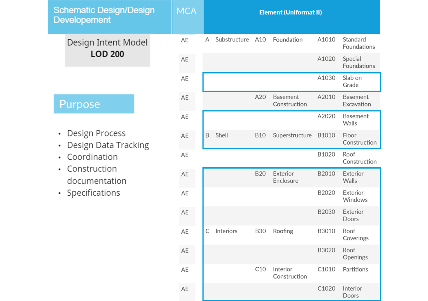
Table 1: LOD 200 Purpose in Schematic Design and Design Development Phases.
Reference: National BIM Standard, version 3.0, 2015
Roles in LOD 200
Defining roles and responsibilities within a project team is a critical first step in ensuring a clear communication path. This step is particularly important for Building Information Management and Building Energy Modeling purposes. There must be a clear designation of which personnel(s) is responsible for the creating, maintaining, and coordinating certain model components. Ideally, all roles should be determined by the time the project reaches Schematic Design or Design Development, in LOD 200.
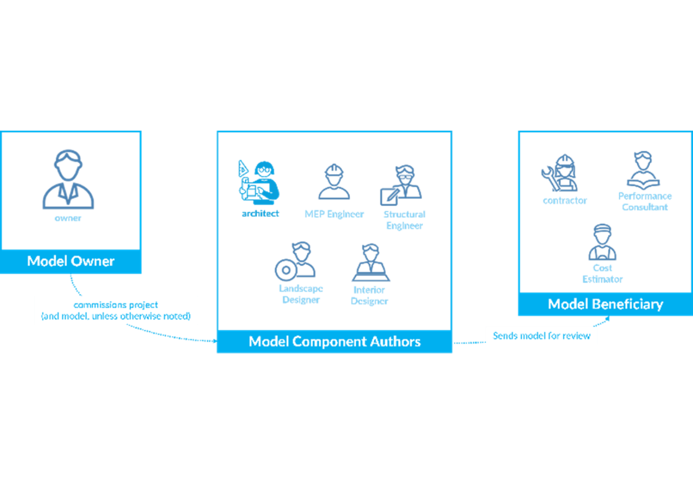
Figure 1: Relationships between parties involved in the creation and usage of BIM
The figure above shows the relationships between Model Owner(s), Model Component Authors, and Model Beneficiaries. Model Owner(s) are typically the party who commissions the project, thereby commissioning the 3D model, unless otherwise noted. The party that is typically responsible for authoring model components (MCA) is comprised of Architects, Engineers, and Designers of various disciplines. Model Beneficiaries are those who use the models created for additional analyses, such as performance analysis, cost, and schedules.
The recommended breakdown of Model Component Authors as aligned within the first three divisions of the Uniformat II work breakdown structure is shown in Table 1. This table references the National Building Information Modeling Standard (NBIMS), version 3.0. In subsequent versions of this document, cove.tool will expand on this table to include Division D, Services, component.
Analyses in LOD 200
Communication and collaboration are essential for the effective implementation of BIM procedures. In a project, multiple disciplines generally utilize different CAD and BIM supporting tools to meet their varying demands. Understanding each tool's features will enable the team to use it to its fullest potential and collaborate and coordinate efficiently.
Typical analyses conducted in this phase include:
1. 3D Massing exploration in Virtual Site (see Figure 2)
3D massing is beneficial to conceptualize the overall building massing indicative of the area, height, volume, location, and orientation using features such as the Mass-In Place/Conceptual Mass in BIM tools.
In BIM tools, this process includes creating multiple models or design iterations through design options in an application like Revit (See Figure 3)
2. Site Planning and Programming
Feasibility studies help examine a property to ascertain its optimal use of land area with local laws and ordinances, and economic viability.
3. Early-Stage energy modeling
Getting early visualization by performing massing site analysis and conceptualizing the environmental impact i.e., solar design of the building
4. Window-to-wall ratios and Glazing orientation (see Figure 4)
Analyze the impact of varying size, spacing and design of the shading strategies and the percentage of Window-to-wall Ratios
5. Preliminary Cost Estimation
The overall mass of a building contains different parameters like level, floor area and floor perimeter, and architects can generate early quantities take-offs from the mass.
6. Preliminary Cost vs Energy Optimization (see Figure 5)
Evaluating assemblies, products, and equipment alternatives while balancing cost and performance metrics.
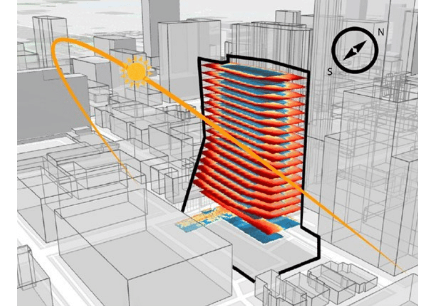
Figure 2: Example of 3D Massing Exploration in Virtual Site, showcasing Daylight Study
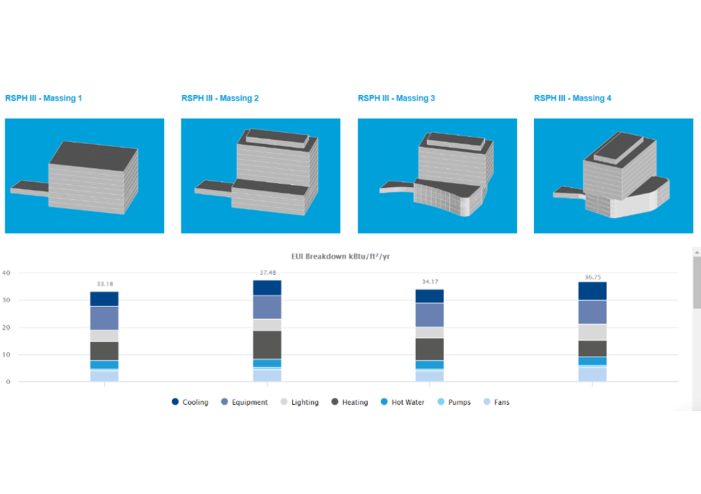
Figure 3: Example of massing comparison with performance data
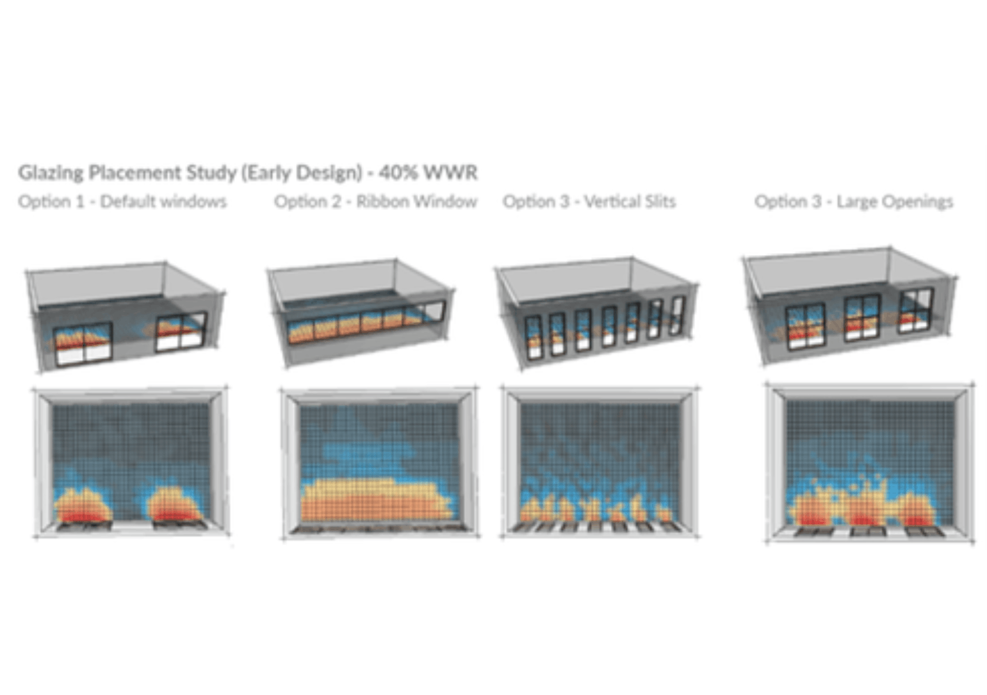
Figure 4: Example of Window-to-Wall Ratio and Glazing Orientation Analysis
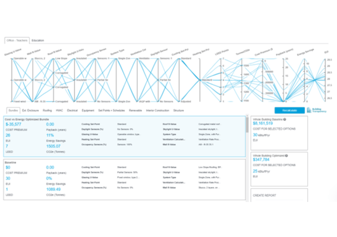
Figure 5: Example of Cost vs Energy Optimization in the cove.tool platform
Deliverables
At the end of each design phase, a project team hands over a deliverable package to the owner and their team. In Schematic Design and Design Development, a deliverable package consists of design documentation in the forms of drawing(s), specification, associated narratives, cost estimate(s), and other supplemental information as deemed necessary by the project team. This information can include an energy model report, documentation for alternatives, and more. While BIM and BEM handoff is not often a required part of the deliverable package in the pre-construction phases, BIM and BEM models are the sources of documentation generation. At the close of SD or DD phases, BIM and BEM can be and are often used for continuing various analyses and further documentation.
Tables 2 and 3 outline the critical information that should be included in LOD 200 BIM. In the Schematic Design phase, a massing model in the form of LOD 200 serves as a means of communication for coordination purposes, with distinct quantities based on the object type. In early Design Development, the quantities and information found in LOD 200 to 300 model(s) are more refined and begin to showcase granular design decisions.
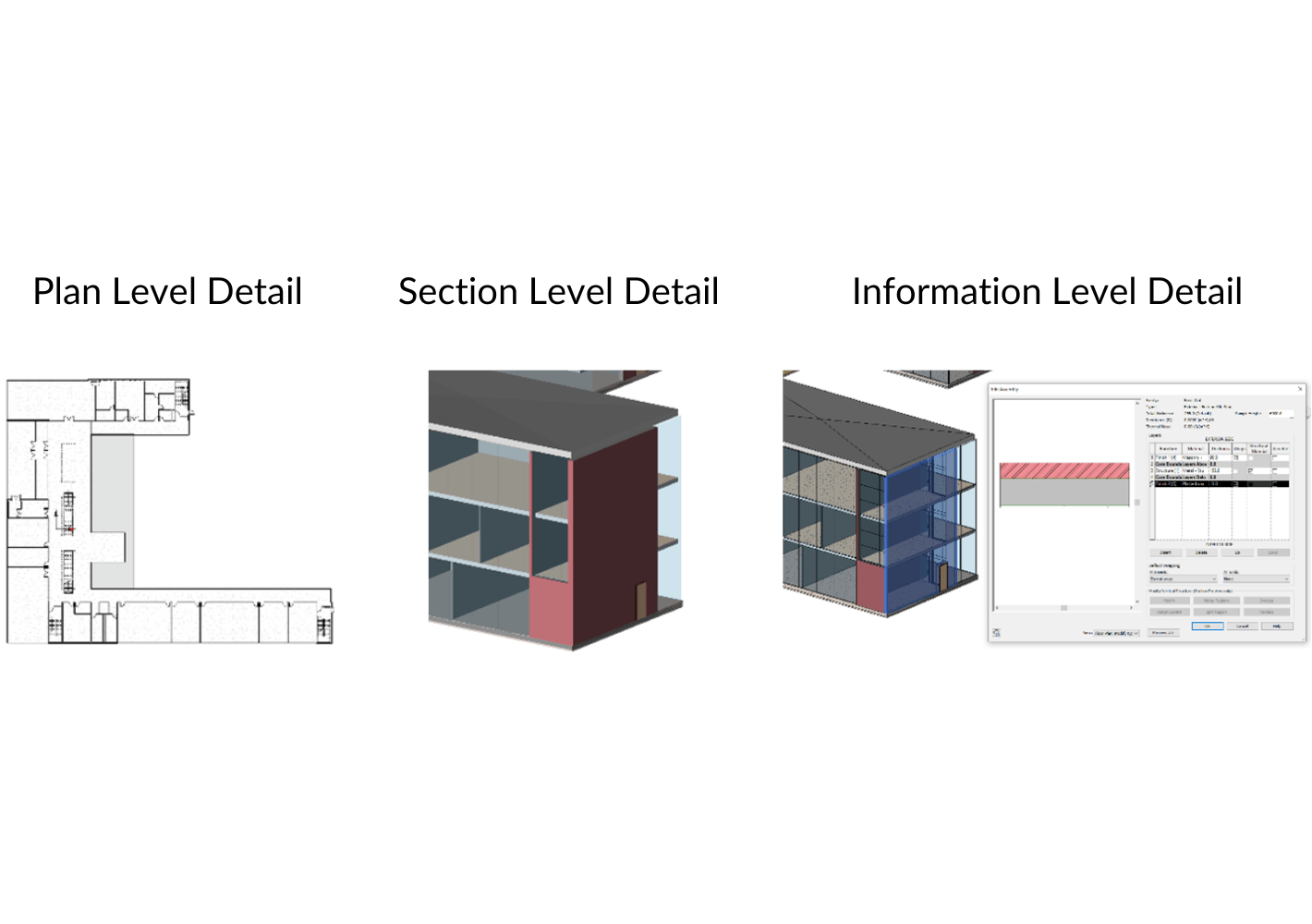
Table 2: Level of Detail (LOD) 200 shown in modeling practice
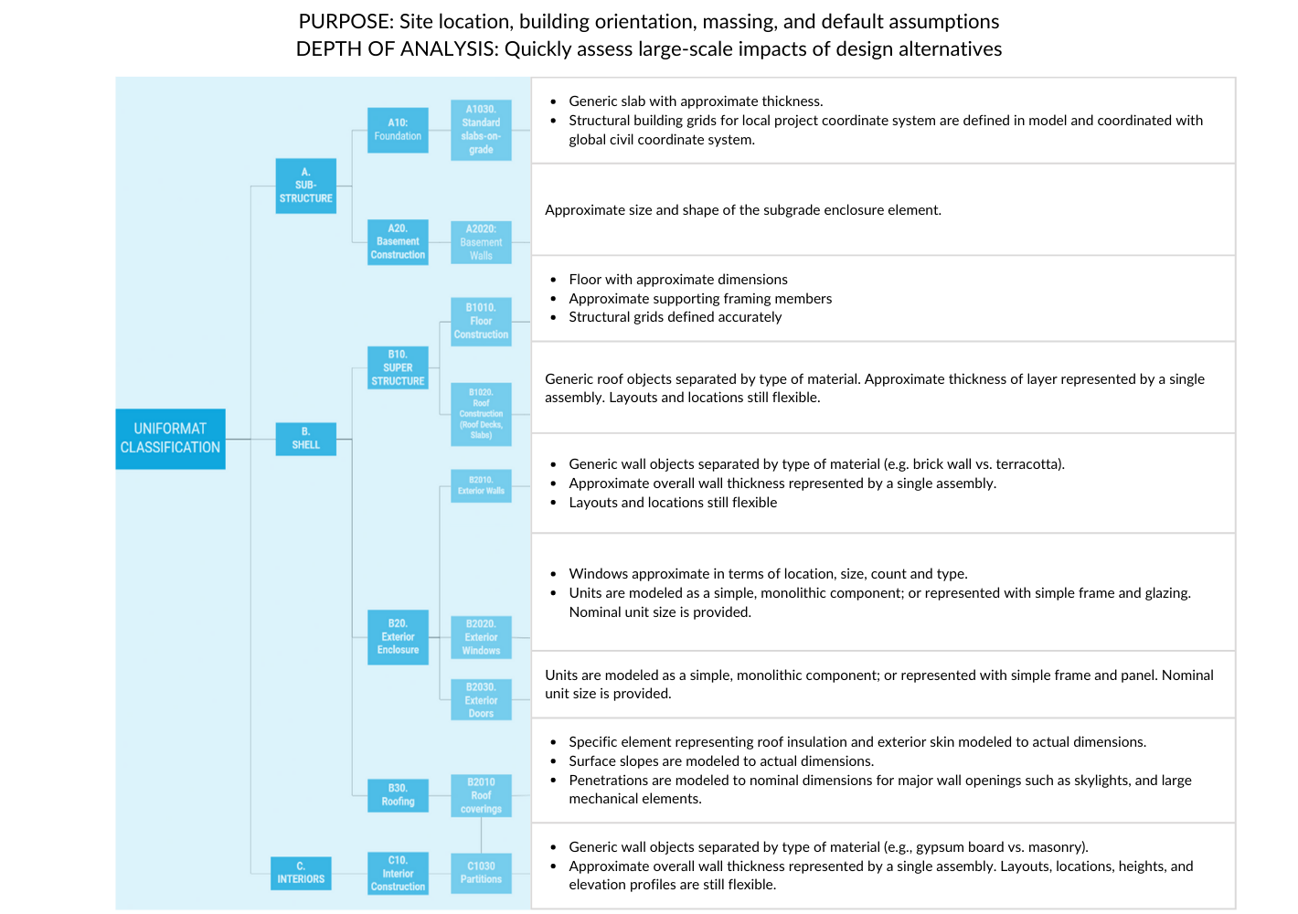
Table 3: Objects to include in LOD 200 Models, aligned with Uniformat II Work Breakdown Structure. Reference: National BIM Standard, version 3.0, 2015
Conclusion
As a building design professional, it's important to utilize the right level of detail (LOD) for analysis and modeling. LOD 200 models are a great choice for the Schematic Design and early Design Development phases since these models offer a good balance between the level of detail and the time and resources required to create them. While they require more effort than LOD 100 models, they are still relatively low compared to LOD 300 and beyond.
By using an automated building performance platform like cove.tool, LOD 200 geometry can provide valuable insights for various aspects of a project, including 3D massing exploration on the virtual site, site planning and programming, early-stage energy modeling, window-to-wall ratios and glazing orientation, preliminary cost estimation, and preliminary cost vs energy optimization.
Continuing to run analyses like these throughout the design process can also improve the design team's workflow by implementing a culture of effective design decision-making based on data and automation. This practice can save time by reducing the need for revisions later on, allowing design professionals to focus on refining their design and sustainability solutions to improve the performance and quality of their projects.
References
2.1 ed., United States General Services Administration (GSA), Washington, DC, 2015, pp. 1–76, GSA BIM Guide 05 – Energy Performance.
3rd ed., National Institute of Building Sciences, Washington, DC, 2015, National BIM Standard - United States® Version 3.
An Architect’s Guide to Integrating Energy Modeling In The Design Process. The American Institute of Architects, 2012.
Bedrick, Jim, et al., editors. BIM Forum, 2020, pp. 1–272, Level of Development (LOD) Specification Part I & Commentary.
Eastman, Chuck, et al. BIM Handbook A Guide to Building Information Modeling for Owners, Managers, Designers, Engineers, and Contractors.
2nd ed., John Wiley & Sons, Inc., 2011. “What Is BIM - Building Information Modeling.” Pluralsight, 5 May 2020, Website Link.
Additional Resources
cove.tool help articles:
Plugin Workflow in Revit for 3D Mode and Daylight
What to avoid in Revit for cove.tool workflow?
Ideal Revit Model for the cove.tool workflow
Ideal modeling workflow of Revit Curtain walls for cove.tool export
Does the Revit Plugin import my project’s material properties?
How does the Revit Plugin Work? Can I create my own View Templates?